2.3.8 Lab – Navigate the IOS by Using Tera Term for Console Connectivity
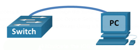
Topology
Objectives
- Part 1: Access a Cisco Switch through the Serial Console Port
- Part 2: Display and Configure Basic Device Settings
- Part 3: (Optional) Access a Cisco Router Using a Mini-USB Console Cable
Note: NetLab users or others using remote access equipment should complete only Part 2.
Instructor Note: Rollover and mini-USB console cables are no longer automatically shipped with the newer routers, such as Cisco 4000 series. These console cables can be purchased from Cisco Systems, Inc. or other third-party vendors.
Background / Scenario
Various models of Cisco routers and switches are used in all types of networks. These devices are managed using a local console connection or a remote connection. Nearly all Cisco devices have a serial console port to which you can connect. Newer models used in this lab, such as Cisco 4221, also have a USB console port.
In this lab, you will learn how to access a Cisco device via a direct local connection to the console port, using the terminal emulation program called Tera Term. You will also learn how to configure the serial port settings for the Tera Term console connection. After you have established a console connection with the Cisco device, you can display or configure device settings. You will only display settings and configure the clock in this lab.
Note: The routers used with CCNA hands-on labs are Cisco 4221 with Cisco IOS XE Release 16.9.3 (universalk9 image). The switches used in the labs are Cisco Catalyst 2960s with Cisco IOS Release 15.0(2) (lanbasek9 image). Other routers, switches, and Cisco IOS versions can be used. Depending on the model and Cisco IOS version, the commands available and the output produced might vary from what is shown in the labs. Refer to the Router Interface Summary Table at the end of the lab for the correct interface identifiers.
Note: Make sure that the switch and router have been erased and have no startup configuration. If you are unsure, contact your instructor.
Instructor Note: Refer to the Instructor Lab Manual for the procedures to initialize and reload devices.
Required Resources
- 1 Router (Cisco 4221 with Cisco IOS XE Release 16.9.3 universal image or comparable)
- 1 Switch (Cisco 2960 with Cisco IOS Release 15.0(2) lanbasek9 image or comparable)
- 1 PC (Windows with a terminal emulation program, such as Tera Term)
- Rollover (DB-9 to RJ-45) console cable to configure the switch or router via the RJ-45 console port
- Mini-USB cable to configure the router via the USB console port
Instructor Note: If Tera Term is not installed on the PC, it can be downloaded from the following link:
Instructor Note: A USB driver must be installed prior to connecting a Microsoft Windows-based PC to a Cisco IOS device with a USB cable. The driver can be found on www.cisco.com with the related Cisco IOS device. The USB driver can be downloaded from the following link:
Instructor Note: You must have a valid Cisco Connection Online (CCO) account to download the USB driver file.
Instructions
Part 1: Access a Cisco Switch through the Serial Console Port
You will connect a PC to a Cisco switch using a rollover console cable. This connection will allow you to access the CLI and display settings or configure the switch.
Step 1: Connect a Cisco switch and computer using a rollover console cable.
a. Connect the rollover console cable to the RJ-45 console port of the switch. Connect the other cable end to the serial COM port on the computer.
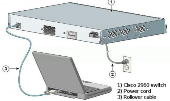
Note: Serial COM ports are no longer available on most computers. A USB-to-DB9 adapter can be used with the rollover console cable for console connection between the computer and a Cisco device. USB-toDB9 adapters can be purchased at any computer electronics retailer.
Note: If using a USB-to-DB9 adapter to connect to the COM port, you may be required to install a driver for the adapter provided by the manufacturer of your computer. To determine the COM port used by the adapter, please see Part 3 Step 3. The correct COM port number is required to connect to the Cisco IOS device using a terminal emulator in Step 2.
b. Turn on the Cisco switch and computer.
Instructions for Packet Tracer: Right-click on the router/switch, select “Inspect Rear” to see the console and USB ports.

Step 2: Configure Tera Term to establish a console session with the switch.
Tera Term is a terminal emulation program. This program allows you to access the terminal output of the switch. It also allows you to configure the switch.
a. Start Tera Term by clicking the Windows Start button located in the task bar. Locate Tera Term under All Programs.
Note: If the program is not installed on the system, Tera Term can be downloaded from the following link by selecting Tera Term:
b. In the New Connection dialog box, click the Serial radio button. Verify that the correct COM port is selected and click OK to continue.
c. From the Tera Term Setup menu, choose the Serial port… to verify the serial settings. The default parameters for the console port are 9600 baud, 8 data bits, no parity, 1 stop bit, and no flow control. The Tera Term default settings match the console port settings for communications with the Cisco IOS switch.
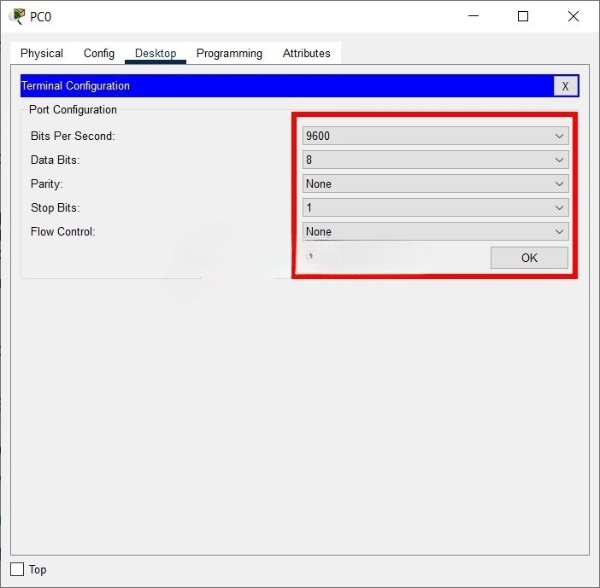
d. When you can see the terminal output, you are ready to configure a Cisco switch.
Part 2: Display and Configure Basic Device Settings
In this section, you are introduced to the user and privileged EXEC modes. You will determine the IOS version, display the clock settings, and configure the clock on the switch.
Step 1: Display the switch IOS image version.
a. After the switch has completed its startup process, the following message is displayed. Enter n to continue.
Would you like to enter the initial configuration dialog? [yes/no]: n
Note: If you do not see the above message, please contact your instructor to reset your switch to the initial configuration.
b. While you are in the user EXEC mode, display the IOS version for your switch.
Switch> show version
Cisco IOS Software, C2960 Software (C2960-LANBASEK9-M), Version 15.0(2)SE, RELEASE
SOFTWARE (fc1)
Technical Support: http://www.cisco.com/techsupport
Copyright (c) 1986-2012 by Cisco Systems, Inc.
Compiled Sat 28-Jul-12 00:29 by prod_rel_team

ROM: Bootstrap program is C2960 boot loader
BOOTLDR: C2960 Boot Loader (C2960-HBOOT-M) Version 12.2(53r)SEY3, RELEASE SOFTWARE
 (fc1)

Switch uptime is 2 minutes
System returned to ROM by power-on
System image file is "flash://c2960-lanbasek9-mz.150-2.SE4.bin"
<output omitted>
Which IOS image version is currently in use by your switch?
c2960-lanbasek9-mz.150-2.SE.bin. Answers will vary depending on the switch.
Step 2: Configure the clock.
As you learn more about networking, you will see that configuring the correct time on a Cisco switch can be helpful when you are troubleshooting problems. The following steps manually configure the internal clock of the switch.
a. Display the current clock settings.
Switch> show clock
*00:30:05.261 UTC Mon Mar 1 1993
b. The clock setting is changed from within the privileged EXEC mode. Enter the privileged EXEC mode by typing enable at the user EXEC mode prompt.
Switch> enable
c. Configure the clock setting. The question mark (?) provides help and allows you to determine the expected input for configuring the current time, date, and year. Press Enter to complete the clock configuration.
Switch# clock set ?
 hh:mm:ss Current Time

Switch# clock set 15:08:00 ?
 <1-31> Day of the month
 MONTH Month of the year

Switch# clock set 15:08:00 Oct 26 ?
 <1993-2035> Year

Switch# clock set 15:08:00 Oct 26 2022
Switch#
*Oct 26 15:08:00.000: %SYS-6-CLOCKUPDATE: System clock has been updated from 00:31:43
UTC Mon Mar 1 1993 to 15:08:00 UTC Fri Oct 26 2012, configured from console by
console.
d. Enter the show clock command to verify that the clock setting has updated.
Switch# show clock
15:08:07.205 UTC Fri Oct 26 2012
Part 3: (Optional) Access a Cisco Router Using a Mini-USB Console Cable
If you are using a Cisco 4221 router, or other Cisco IOS devices with a mini-USB console port, you can access the device console port using a mini-USB cable connected to the USB port on your computer.
Note: The mini-USB console cable is the same type of mini-USB cable that is used with other electronics devices, such as USB hard drives, USB printers, or USB hubs. These mini-USB cables can be purchased from Cisco Systems, Inc. or other third-party vendors. Please verify that you are using a mini-USB cable, not a micro-USB cable, to connect to the mini-USB console port on a Cisco IOS device.

Note: You must use either the USB port or the RJ-45 port. Do not use both ports simultaneously. When the USB port is used, it takes priority over the RJ-45 console port.
Step 1: Set up the physical connection with a mini-USB cable.
a. Connect the mini-USB cable to the mini-USB console port of the router. Connect the other cable end to a USB port on the computer.
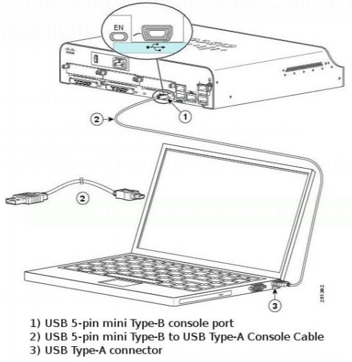
On Packet Tracer:
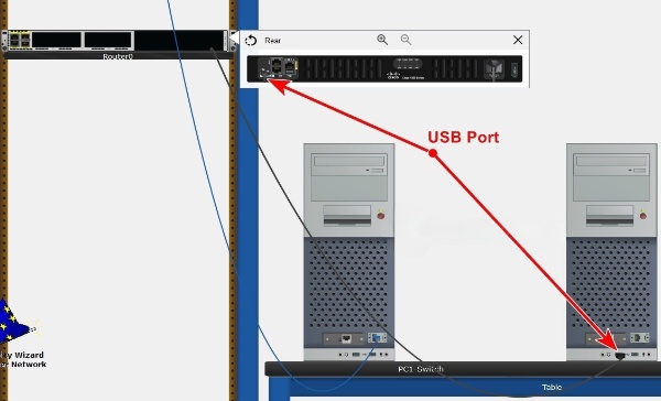
b. Turn on the Cisco router and computer.
Step 2: Verify that the USB console is ready.
If you are using a Microsoft Windows-based PC and the USB console port LED indicator (labeled EN) does not turn green, please install the Cisco USB console driver.
A USB driver must be installed prior to connecting a Microsoft Windows-based PC to a Cisco IOS device with a USB cable. The driver can be found on www.cisco.com with the related Cisco IOS device. The USB driver can be downloaded from the following link:
Note: You must have a valid Cisco Connection Online (CCO) account to download this file.
Note: This link is related to the Cisco 1941 router. However, the USB console driver is not Cisco IOS devicemodel specific. This USB console driver only works with Cisco routers and switches. The computer requires a reboot after finishing the installation of the USB driver.
Note: After the files are extracted, the folder contains instructions for installation, removal, and the necessary drivers for different operating systems and architectures. Please choose the appropriate version for your system.
When the LED indicator for the USB console port has turned green, the USB console port is ready for access.
Step 3: (Optional) Enable the COM port for the Windows 7 PC.
If you are using a Microsoft Windows 7 PC, you may need to perform the following steps to enable the COM port:
a. Click the Windows Start icon to access the Control Panel.
b. Open the Device Manager.
c. Click the Ports (COM & LPT) tree link to expand it. Right-click the USB Serial Port icon and choose Update Driver Software.
d. Choose Browse my computer for driver software.
e. Choose Let me pick from a list of device drivers on my computer and click Next.
f. Choose the Cisco Serial driver and click Next.
g. Note the port number assigned at the top of the window. In this sample, COM 5 is used for communication with the router. Click Close.
h. Open Tera Term. Click the Serial radio button and choose the appropriate serial port, which is Port COM5: Cisco Serial (COM 5) in this example. This port should now be available for communication with the router. Click OK.
Reflection Question
1. How do you prevent unauthorized personnel from accessing your Cisco device through the console port?
Physically secure the device and use password protection
2. What are the advantages and disadvantages of using the serial console connection compared to the USB console connection to a Cisco router or switch?
It depends on the port availability on the PC and the router or switch. If the PC has a serial port and a DB9-to-RJ45 cable is available, it is generally easier to connect to the router or switch using the serial console port. If the PC does not have a serial port, a third party USB-to-Serial adapter can be used. Cisco switches do not have mini-USB console ports, so connecting via USB is not an option. If you are frequently connecting to a Cisco router that has a mini USB console port, this can be the most effective method after the Cisco drivers are installed because nearly all newer PCs have USB ports.
Router Interface Summary Table
| Router Model | Ethernet Interface #1 | Ethernet Interface #2 | Serial Interface #1 | Serial Interface #2 |
|---|---|---|---|---|
| 1800 | Fast Ethernet 0/0 (F0/0) | Fast Ethernet 0/1 (F0/1) | Serial 0/0/0 (S0/0/0) | Serial 0/0/1 (S0/0/1) |
| 1900 | Gigabit Ethernet 0/0 (G0/0) | Gigabit Ethernet 0/1 (G0/1) | Serial 0/0/0 (S0/0/0) | Serial 0/0/1 (S0/0/1) |
| 2801 | Fast Ethernet 0/0 (F0/0) | Fast Ethernet 0/1 (F0/1) | Serial 0/1/0 (S0/1/0) | Serial 0/1/1 (S0/1/1) |
| 2811 | Fast Ethernet 0/0 (F0/0) | Fast Ethernet 0/1 (F0/1) | Serial 0/0/0 (S0/0/0) | Serial 0/0/1 (S0/0/1) |
| 2900 | Gigabit Ethernet 0/0 (G0/0) | Gigabit Ethernet 0/1 (G0/1) | Serial 0/0/0 (S0/0/0) | Serial 0/0/1 (S0/0/1) |
| 4221 | Gigabit Ethernet 0/0/0 (G0/0/0) | Gigabit Ethernet 0/0/1 (G0/0/1) | Serial 0/1/0 (S0/1/0) | Serial 0/1/1 (S0/1/1) |
| 4300 | Gigabit Ethernet 0/0/0 (G0/0/0) | Gigabit Ethernet 0/0/1 (G0/0/1) | Serial 0/1/0 (S0/1/0) | Serial 0/1/1 (S0/1/1) |
Note: To find out how the router is configured, look at the interfaces to identify the type of router and how many interfaces the router has. There is no way to effectively list all the combinations of configurations for each router class. This table includes identifiers for the possible combinations of Ethernet and Serial interfaces in the device. The table does not include any other type of interface, even though a specific router may contain one. An example of this might be an ISDN BRI interface. The string in parenthesis is the legal abbreviation that can be used in Cisco IOS commands to represent the interface.
